As a supplier of robot brushless motors, I’ve had the privilege of witnessing the transformative power of these motors in the robotics industry. One of the most critical aspects of a robot brushless motor is its commutation method. In this blog post, I’ll delve into the details of what commutation is, the different commutation methods available, and their implications for robot applications. Robot Brushless Motor

Understanding Commutation in Brushless Motors
Before we explore the commutation methods, let’s first understand what commutation means in the context of a brushless motor. In a traditional brushed DC motor, the commutator and brushes are responsible for switching the direction of the current in the armature windings as the motor rotates. This switching action ensures that the magnetic field produced by the armature interacts with the magnetic field of the stator in such a way that the motor continues to rotate.
In a brushless motor, however, there are no brushes or commutators. Instead, electronic circuits are used to perform the commutation function. The electronic commutation system determines when and how the current is applied to the motor’s windings to generate the required torque and speed.
Different Commutation Methods
Sensor – Based Commutation
- Hall – Effect Sensors
Hall – effect sensors are the most commonly used sensors for commutation in brushless motors. These sensors detect the presence and direction of a magnetic field. In a brushless motor, Hall – effect sensors are placed around the stator to sense the position of the rotor’s magnetic field.
The Hall – effect sensors produce digital signals that indicate the position of the rotor. Based on these signals, the electronic controller determines which motor windings should be energized at any given time. For example, in a three – phase brushless motor, the Hall – effect sensors provide information about the 60 – degree intervals of the rotor’s rotation. The controller uses this information to switch the current between the three phases in a specific sequence, creating a rotating magnetic field that drives the rotor.
The advantage of using Hall – effect sensors is their reliability and simplicity. They are relatively inexpensive and can provide accurate position information. However, they do add some complexity to the motor design and can be affected by temperature and magnetic interference.
- Encoder – Based Commutation
Encoders are another type of sensor that can be used for commutation. There are two main types of encoders: optical encoders and magnetic encoders.
Optical encoders use a light – emitting diode (LED) and a photodetector to detect the position of a rotating disk with a pattern of opaque and transparent sections. As the disk rotates, the photodetector senses the changes in light intensity, generating a series of pulses that represent the position of the rotor.
Magnetic encoders, on the other hand, use a magnetic field to detect the position of the rotor. They are more robust than optical encoders and are less affected by dust, dirt, and moisture.
Encoder – based commutation provides very high precision in determining the rotor position. This is particularly useful in applications where accurate speed and position control are required, such as robotic arms and precision manufacturing equipment. However, encoders are more expensive than Hall – effect sensors and require more complex signal processing.
Sensorless Commutation
- Back – EMF Detection
Back – electromotive force (back – EMF) is the voltage generated in the motor windings as the rotor rotates. In a brushless motor, the back – EMF is proportional to the speed of the motor and the strength of the magnetic field.
Sensorless commutation using back – EMF detection works by measuring the back – EMF in the non – energized motor windings. When the back – EMF crosses a certain threshold, it indicates that the rotor has reached a specific position. The controller then switches the current to the appropriate windings to continue the rotation.
The main advantage of back – EMF detection is the elimination of position sensors. This reduces the cost and complexity of the motor system and makes it more reliable in harsh environments. However, back – EMF detection has some limitations. It is not suitable for low – speed operation because the back – EMF is very small at low speeds. Additionally, it can be affected by motor load and electrical noise.
- Inductance – Based Methods
Inductance – based sensorless commutation methods rely on the fact that the inductance of the motor windings changes as the rotor rotates. By measuring the changes in inductance, the position of the rotor can be estimated.
One approach is to inject a high – frequency signal into the motor windings and measure the response. The changes in the inductance of the windings cause changes in the impedance, which can be detected by the controller.
Inductance – based methods can work at very low speeds and are less affected by load variations compared to back – EMF detection. However, they are more complex to implement and require sophisticated signal processing algorithms.
Implications for Robot Applications
The choice of commutation method has significant implications for robot applications.
In applications where cost is a major concern, such as consumer robots or hobbyist projects, sensor – based commutation with Hall – effect sensors or sensorless commutation using back – EMF detection may be the preferred choice. These methods offer a good balance between cost and performance.
For industrial robots and high – precision applications, encoder – based commutation is often the best option. The high precision of encoders allows for accurate control of the robot’s motion, which is essential for tasks such as pick – and – place operations, welding, and assembly.
In harsh environments where sensors may be damaged or unreliable, sensorless commutation methods like back – EMF detection or inductance – based methods are more suitable. They can provide a reliable operation without the need for external sensors.
Conclusion
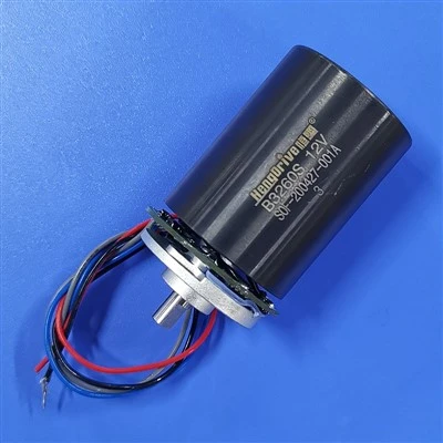
In conclusion, the commutation method of a robot brushless motor is a crucial factor that determines the performance, cost, and reliability of the motor system. As a supplier of robot brushless motors, I understand the importance of choosing the right commutation method for each application. Whether it’s sensor – based commutation for high – precision tasks or sensorless commutation for cost – effective and robust solutions, we offer a wide range of motor options to meet the diverse needs of our customers.
Medical Brushless Motor If you’re in the market for robot brushless motors and want to discuss the best commutation method for your specific application, I encourage you to reach out to our sales team. We have the expertise and experience to help you select the optimal motor solution for your robot project.
References
- Krause, P. C., Wasynczuk, O., & Sudhoff, S. D. (2013). Analysis of electric machinery and drive systems. John Wiley & Sons.
- Chiasson, J. N. (2005). Modeling and high-performance control of electric machines. Wiley-IEEE Press.
- Bolton, W. (2016). Mechatronics: electronic control systems in mechanical and electrical engineering. Newnes.
Shenzhen HengDrive Technologies Co., Ltd.
Shenzhen HengDrive Technologies Co., Ltd. is one of the most professional robot brushless motor manufacturers and suppliers in China, specialized in providing high quality customized service. We warmly welcome you to buy the newest robot brushless motor in stock here from our factory.
Address: Building A & F, FuNing Hi-Tech Park, XinTian Road, FuHai Street, BaoAn District, ShenZhen, GuangDong Province, China.
E-mail: Marketing001@hengdrive.com
WebSite: https://www.hengdrivemotor.com/
